Effect of Tower Footing Resistance in having glitch-free T&D lines
By EPR Magazine Editorial March 7, 2022 5:46 pm IST


By EPR Magazine Editorial March 7, 2022 5:46 pm IST

This article talks about dealing with the susceptible glitches in T&D lines and ensuring uninterrupted power supply.
Large overhead transmission lines are exposed to unpredictable and continued atmospheric aging. In addition, a lightning strike on a tower may degenerate into an electrical fault that can cripple the transmission system, leading to operational interruptions and many cascading incidents and accidents. Therefore, maintaining these lines is critical to ensuring an uninterrupted power supply for all operations.
Additionally, transmission networks are susceptible to series and short-circuit faults caused by line breakage or tower deformation due to storms or high winds. To minimise the hazardous impacts of such faults, immediate fault clearing and dissipation is critical.
By achieving low tower footing resistance (TFR), lightning and earth fault current can dissipate effectively through the lowest resistance path to earth without flashing over the transmission tower insulator. However, when the TFR is high, back-flashover voltage across the insulator of transmission lines may occur, converting the lightning to an earth fault. High TFR may also delay the clearance of an earth fault.
Each transmission tower requires low tower footing resistance (TFR), which depends on soil resistivity. The three parameters affecting soil resistivity are moisture, salt, and soil temperature. Whenever lightning strikes on the top of a transmission tower or earth wire, a lightning current flows towards the bottom of the tower, causing the voltage to rise till the current density in the soil increases sufficiently to ionise the soil. After soil ionisation, impedance is reduced substantially, lowering the stress across the insulator. However, as mentioned earlier, the high stresses created before soil ionisation can result in back flashover across the insulators. The probability of flashovers can be minimised if there is sufficient moisture between the grains of soil, enabling critical current density to be reached faster for soil ionisation.
Tower footing resistance for fast front surges is not very well understood. However, the impulse ground resistance is less than the measured or calculated resistance because significant ground current causes soil ionisation. Therefore, a variable grounding resistance approximation can be applied, which is surge current dependent as per the following equation.
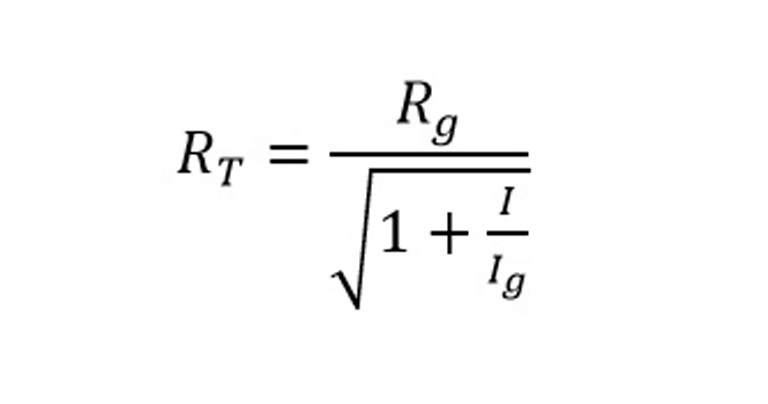
Where,
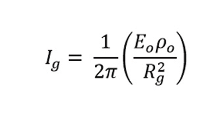
Where,
Adapting IIoT products such as Remote Fault-time Earth Resistance Monitoring (R-FERM), an advanced patented technology (Patent no. 381603), allows condition monitoring of the transmission tower’s grounding system. It monitors the Rgo of each transmission tower during normal and fault-time conditions and alerts O&M personnel to take appropriate action before the system fails completely. Knowing the location requires focused action, reduces O&M costs, and eliminates unplanned network failures. This can be the first step in digitising transmission and distribution maintenance.
For more details, visit, http://manavenergy.com
We use cookies to personalize your experience. By continuing to visit this website you agree to our Terms & Conditions, Privacy Policy and Cookie Policy.


-20251010140647.jpg)


-20251007141246.jpg)


-20251010134742.jpg)