Earthing resistance and measurement practices
By EPR Magazine Editorial June 12, 2020 10:33 am IST


By EPR Magazine Editorial June 12, 2020 10:33 am IST

According to statistics of National Crime Records Bureau (NCRB), 2,255 persons died due to accidental fires caused by electrical short circuits in the year 2015, which was a 25 percent rise from 2014 and a 48 percent jump from 2011. Most short circuit fires have been triggered by loose wiring, bad quality electrical fittings (improper earthing/connections) or poor maintenance of wiring work.
Importance of measuring earth resistanceThe content of moisture changes seasonally, varies according to the sub layers of earth and also the depth of the permanent water table. Soil and water are generally more stable at deeper strata. So, the ground rods are placed as deep as possible into the earth, at the water table if possible. Also, the installation of ground rods should be at a stable temperature, i.e., below the frost line. If the grounding system is designed to withstand the worst possible conditions, then the system is considered as an effective grounding system.
Factors affecting grounding resistance
The resistance value is given as:
R=p l/a
So, the factors affecting earth resistance are:
Length/depth of the ground electrode: Resistivity of soil is not consistent; hence, it becomes unpredictable. Deeper the soil level, lower is the resistivity of soil. Hence, driving ground electrodes deeper is an effective way to lower ground resistance.
Diameter of the ground electrode: Increasing the diameter of the ground electrode results in lowering the resistance of the electrode.
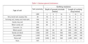
Number of ground electrodes: The ground resistance can be lowered using multiple ground electrodes. More than one electrode is connected in parallel and driven into the ground to lower the resistance. Table 1 provides various ground resistances.
Ground system design
If a single electrode is driven into the ground, it is considered as a simple grounding system. This is the most common grounding practice. If grounding systems consist of multiple ground rods, connected, mesh or grid networks, ground plates, and ground loops, then the system is considered as complex grounding. These systems are preferably installed at power generating substations, central offices, and cell phone tower sites.
Methods to measure ground resistance
P = 2 π A R where:
P= the average soil resistivity to depth A in: ohm-cm
π = 31,416
A = the distance between the electrodes in cm
R = the measured resistance value in ohm
Fall of potential
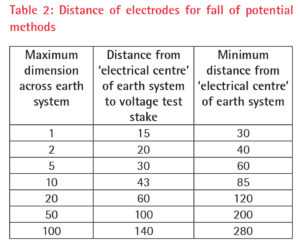
The outer test electrode, or current test stake, is driven into the ground 30 to 50 metres away from the earth system. This distance will depend on the size of the system being tested as shown in the table below, and the inner electrode, or voltage test stake, is then driven into the ground midway (50 percent distance) between the earth electrode and the current test stake, and in a direct line between them. This method includes a check to ensure that the test electrodes are actually positioned far enough away for a correct reading to be obtained. Two additional measurements should be made for corrected measurement:
The 62 percent method
A slight modification in the fall of potential method makes it suitable for medium-sized earthing systems. This modification is stated as the 62 percent method. It involves positioning the inner test stake at 62 percent of the earth electrode from outer stake separation. Some of the disadvantages with this method are:
The slope method
For a large system, it is not possible to measure the earth resistance by fall of potential methods due to limitation of electrodes. Hence, the slope method is suitable for use with large earthing systems, such as power substation earth. This method is similar to the fall of potential method, but includes taking a number of resistance measurements at various earth systems to voltage electrode separations. After measurement, it is required to plot a graph of the resistance variation between the earth and the current to find the optimal resistance.
The star-delta method
This method suits best when used with large systems in builtup areas or on rocky terrain, where placing of test electrodes is difficult, especially in a straight line over a long distance. In this method, there are three electrodes that are set up at the corners forming an equilateral triangle with the earth system in the middle. The total resistance between adjacent electrodes is taken into consideration for measurement purpose and also between each electrode and earthing system.
The four-potential method (Wenner method) In this method, four electrodes are placed in a line into the ground, which are equally spaced at a distance “a” from each other. A generator is used to inject a current “I” between the two outer electrodes (E and H), which is then used for measurement. The potential rV is then measured with a voltmeter between the two central electrodes (S and ES).
Standards for earth resistance measurement
Authored by: Komal Bhandare, Deepak Nikam, and Anil Gadhe (IS Department)
We use cookies to personalize your experience. By continuing to visit this website you agree to our Terms & Conditions, Privacy Policy and Cookie Policy.


-20240706113929.png)