Optimising Safety, Surge arrester voltage selection tailored to system earthing configurations
By EPR Magazine Editorial February 2, 2024 3:55 pm IST


By EPR Magazine Editorial February 2, 2024 3:55 pm IST

A surge arrester, a device for limiting overvoltage transients in power networks, clamps these surges by conducting excess current to the ground, protecting equipment and power flow. The right arrester choice hinges on application, protection level, and system traits, considering factors like voltage and current ratings, energy absorption, type, response time, environment, and manufacturer credibility. This article focuses on selecting appropriate voltage levels for surge arresters according to system grounding configurations.
Definitions:
Continuous Operating Voltage (Uc): The maximum power-frequency voltage that can be continuously applied across an arrester’s terminals.
Discharge Current: The impulse current flowing through an arrester during a surge.
Rated Voltage (Ur): The highest 10-second power frequency voltage an arrester can handle, confirmed by TOV, operating duty tests, and a key reference for operating specifications.
Residual Voltage (Ures): The peak voltage across an arrester’s terminals during discharge current passage, also known as “discharge voltage” in some regions.
Surge arresters, previously known as Lightning Arresters, protect electrical systems from voltage spikes, including those caused by lightning, switching operations, and ground faults. They function by momentarily breaking down their insulation to discharge voltage surges to the ground and then restore insulation once voltage drops below a set value, stopping further current flow to the ground. Modern systems primarily use gapless zinc oxide (ZnO) surge arresters. (Refer figure 2)
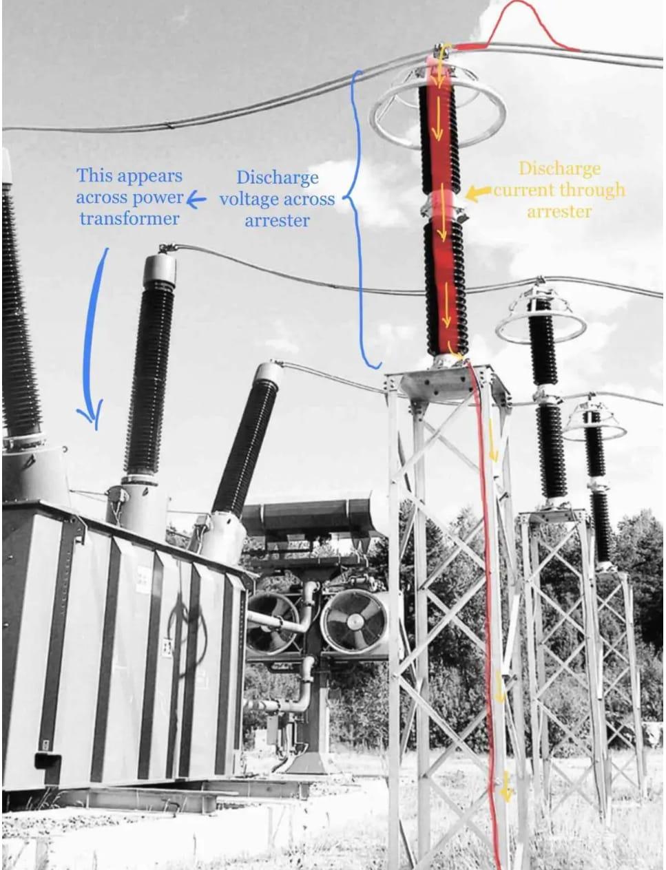
Fig 2 SURGE ARRESTER DISCHARGE PATH
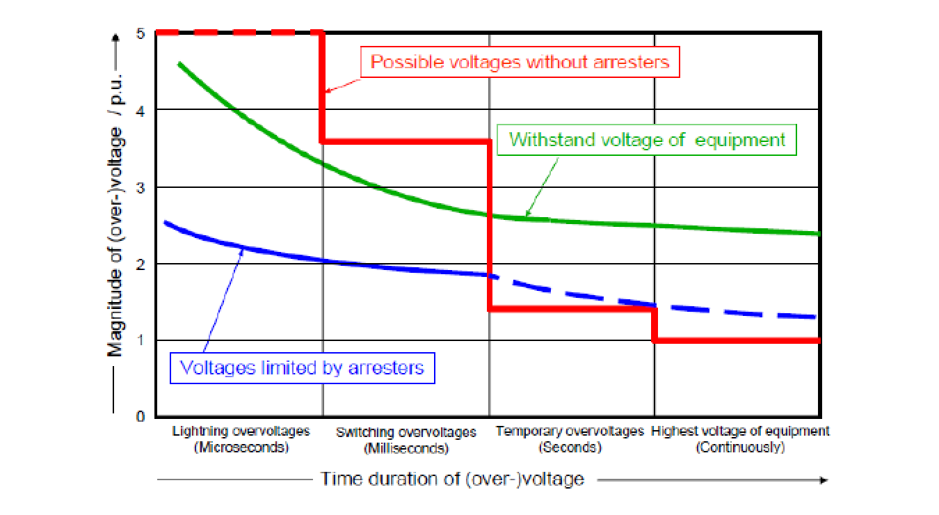
For effective protection, surge arresters must block ground current under normal voltage, provide a grounding path for voltage surges above a certain level without increasing circuit voltage, and stop ground current flow, restoring insulation once voltage drops. Following energy ratings and operational tests, they must withstand repeated discharges without damage. A surge arrester’s effectiveness relies on a solid ground connection; it’s ineffective without one and should be installed close to the protected equipment with short, direct ground leads. Surge arresters don’t absorb or stop lightning but divert it to the ground, clamping the resulting voltage and only protecting equipment electrically parallel to them. (Refer Figure 3)
Fig 3 VOLTAGE CLAMPING BY SURGE ARRESTERS
Overvoltages
Power systems often experience overvoltages exceeding normal levels due to factors like lightning, circuit breaker operations, or conductor grounding. While not always severe, these overvoltages can impact circuit interrupters and protective devices and sometimes cause insulation breakdown in system equipment. Engineers work to limit and control these overvoltages, known as voltage surges or transient voltages. Overvoltages are categorised into external (lightning-induced, either direct or indirect) and internal types, including power frequency, resonance, and switching overvoltages.
The classification is shown in Figure 4.
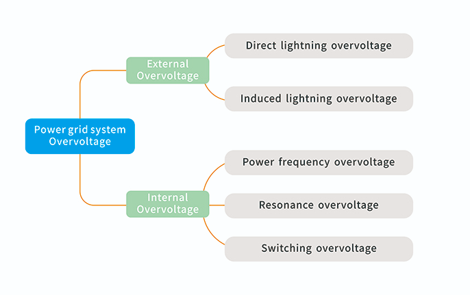
Fig 4 OVER VOLTAGE IN POWER SYSTEM- LOCATION BASED
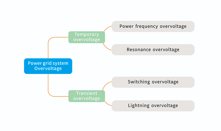
Overvoltages in power systems are classified into temporary and transient types based on duration. Temporary overvoltages, like power frequency and resonance overvoltages, last longer and depend on the system’s structure, capacity, operation mode, fault conditions, and protective device characteristics. Transient overvoltages, including switching and lightning overvoltages, are much shorter, ranging from microseconds to milliseconds. They can be further divided into fast wavefront overvoltages, lasting 0.1 to 20 microseconds, and slow wavefront overvoltages, peaking between 20 and 5000 microseconds.The classification is shown in Figure 5
Fig 5 OVER VOLTAGE IN POWER SYSTEM – TIME DURATION BASED
The typical waveform of overvoltage is as follows, as shown in Figure 6.
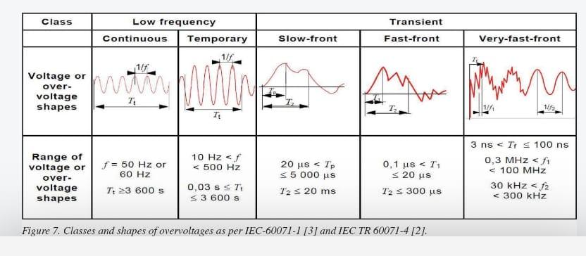
Fig 6 DIFFERENT TYPES OF SURGES IN POWER SYSTEM
Surge arrester general selection criteria
The goal in selecting a surge arrester is to choose the lowest-rated one that still ensures adequate protection of equipment insulation and offers a satisfactory lifespan when connected to the power system. Opting for the minimum rating maximizes the protection margin for the insulation. While a higher-rated arrester may have better survival capability on the power system, it offers less protective margin for the insulation. Therefore, the selection process must balance the arrester’s durability and protective efficiency for equipment. Understanding the Voltage Current Characteristics of the Zno Block in the surge arrester is crucial for this decision.
Figure 7 below shows the V-I characteristics of ZnO element which are divided into three regions, being low current region (A), operating region (B) and high current region (C).
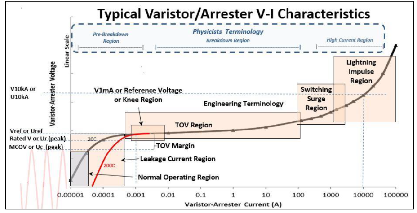
Fig 7 V-I CHARACTERISTICS of ZnO SURGE ARRESTER
The class of lightning arrester to be applied depends upon the importance and value of the protected equipment, its impulse insulation level and the expected discharge currents the arrester must withstand. Protection class as per IEC standard is given in table 1.
TABLE 1 SURGE ARRESTER CLASS (OLD & NEW CLASSIFICATION)
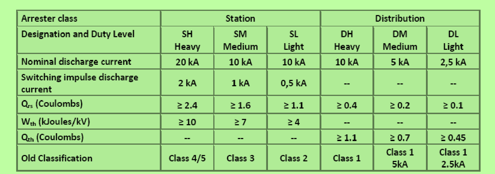
The letters “H”, “M” and “L” in the designation stand for “high”, “medium” and “low” duty, respectively.
Qrs=Repetitive Charge Transfer Rating (introduced in the newly released IEC 60099-4 in 2014 & adopted by IS 15086-4 in 2017)
Wth= Thermal Energy Rating
Qth= Thermal Charge Transfer Rating
Note : This new classification system now replaces the old classification system Class 1, 2, 3, 4 & 5.
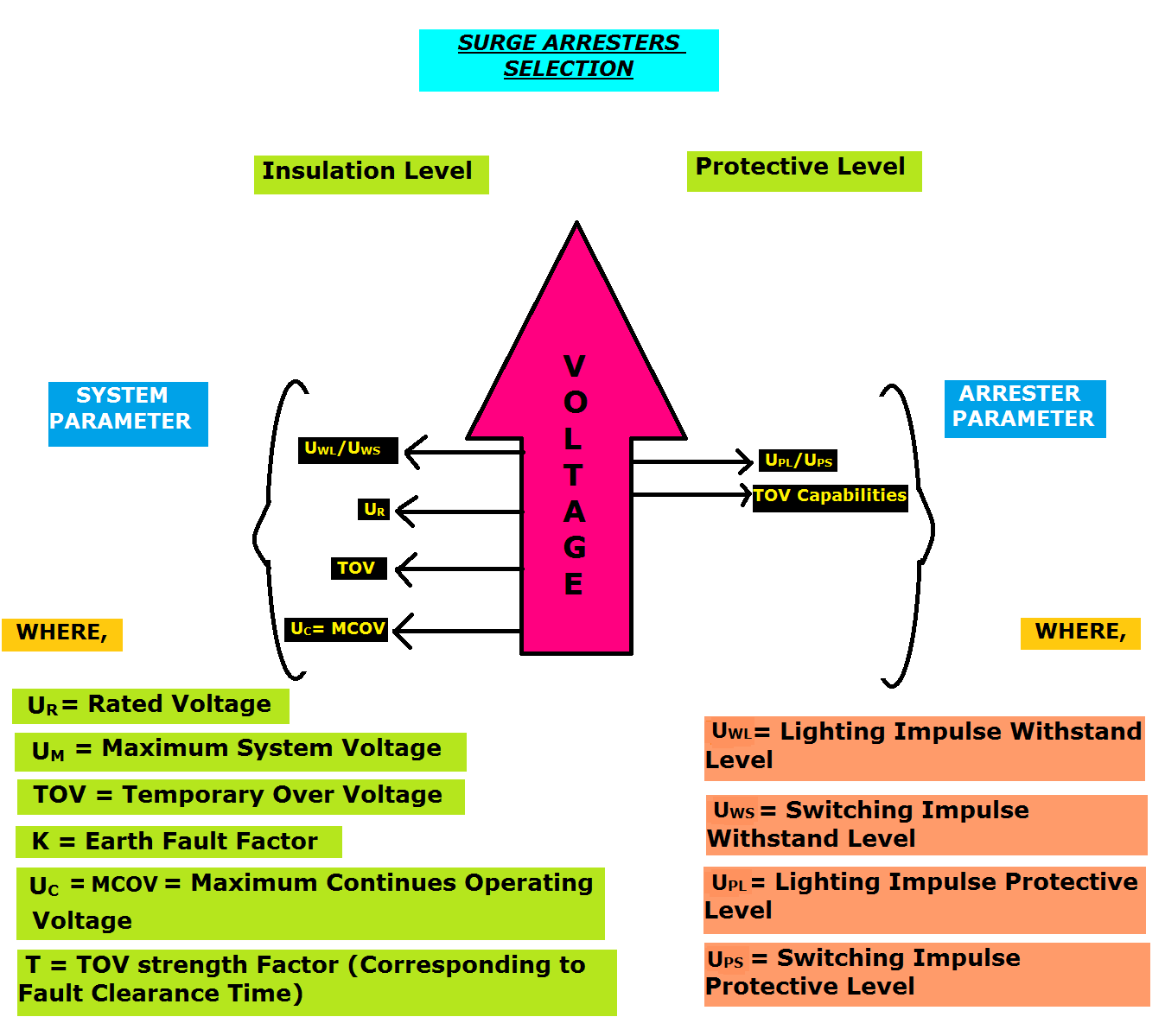
Fig 8 SURGE ARRESTER SELECTION CRITERIA
Overall surge arrester selection method is depicted in the figure 8 & margin of protection is illustrated in figure 9 respectively.
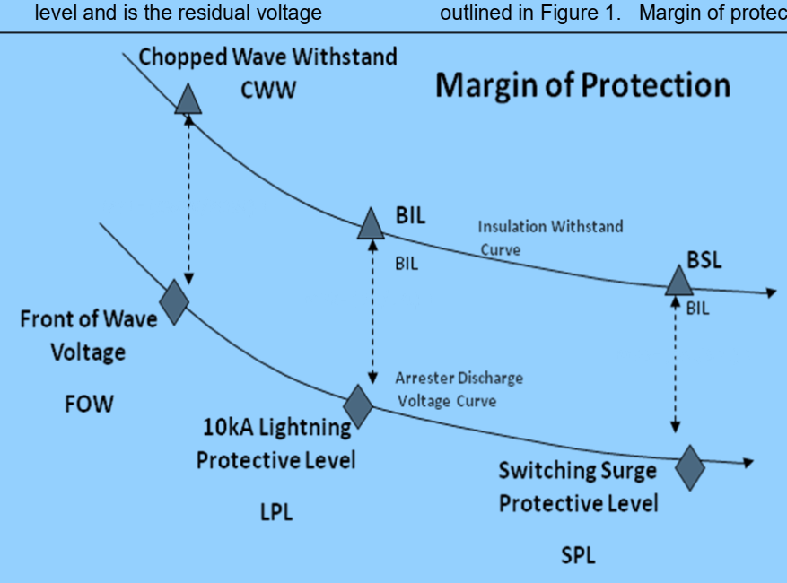
Fig 9 SURGE ARRESTER – MARGING OF PROTECTION
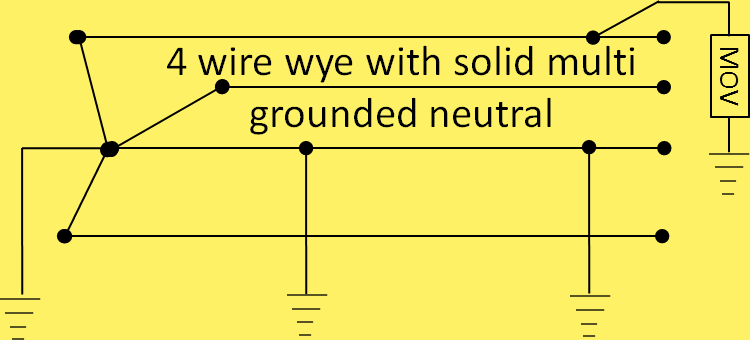
Selecting a surge arrester’s voltage involves understanding the system voltages and determining the system configuration, such as whether it’s a wye (star) or delta system. Additionally, it’s important to know the role of the system’s neutral conductor, if present. The power source transformer and the neutral bonding scheme affect the potential rise in line-to-ground voltage of unfaulted phases during a ground fault. Luckily, the variety of system configurations to consider is limited.The most common configuration is the 4 wire solid multi-grounded neutral as shown in figure 10. This is also known as an effectively grounded system.
Fig 10 SOLIDLY MULTI-GROUNDED 4 WIRE SYSTEM
The three-wire impedance grounded wye (or star) system is a prevalent industrial configuration. Its popularity stems from its ability to limit earth fault current via impedance—low impedance limits fault current, allowing for lower-rated equipment and often reducing costs. With high impedance, a Petersen coil is employed, providing fault-extinguishing capabilities without needing breakers, known as a resonant grounded system.(Refer figure 11)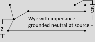
Fig 11 IMPEDANCE OR RESONANT GROUNDED SYSTEM
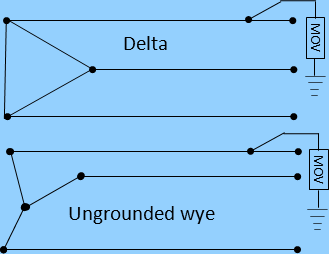
A third common system configuration is an isolated or ungrounded system. This can be either delta or wye configured. Figure 12 shows these two systems.
Fig 12 UNGROUNDED SYSTEMS (ISOLATED NEUTRAL)
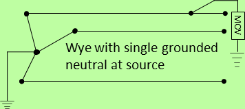
A common transmission line configuration is the single grounded Wye as seen in Figure 13.
Fig 13 SINGLE GROUNDED NEUTRAL SYSTEM (UNI-GROUNDED)
Determining phase voltage rise due to earth or ground faults
When a three-phase power system has a ground fault, the voltage between phase and ground increases for the unfaulted phases, affecting surge arresters connected between the phase conductor and earth. This voltage spike persists until a breaker interrupts the fault, a crucial factor in selecting an arrester’s voltage rating. Precisely calculating this voltage rise during a ground fault is challenging, often relying on basic rules or graphs. A worst-case scenario approach is adopted for distribution systems with uncertain transformer and system impedances, where the voltage rise is estimated by multiplying the line-to-ground voltage by a ground fault factor.
Table 2 lists the ground fault factors used to determine the unfaulted phase voltage rise during a ground fault.
TABLE 2 Earth (Ground) Fault Factor
Type of System (w.r.t transformer vector group ) | Ground Fault Factor |
| Solidly Grounded 4 wire systems | 1.25 |
| Uni-grounded 3 wire systems | 1.4 |
| Impedance grounded systems | 1.73 |
| Isolated Ground Systems and Delta Systems | 1.73 |
Note 1 : Two factors may be used to measure this type of overvoltage
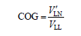
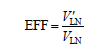
where V’LN is the maximum phase-to-ground voltage on the unfaulted phases during a fault, and VLN, VLL, are respectively the nominal phase-to-neutral and phase-to-phase voltages.
Obviously: EFF = 1.73 COG
It is also important to note that the grounding of the neutral at the source transformer is the configuration referred to in determining the voltage rise of the system.
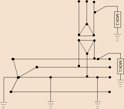
Fig 14 MIXED CONFIGURATION
For example as seen in Figure 14, a delta/delta transformer is tied to a solidly grounded wye system. In this case MOV1 should be sized for a solidly grounded system, and MOV 2 should be sized for an isolated ground system.
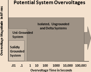
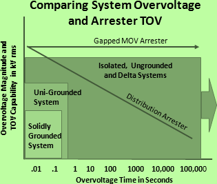
After the system configuration and potential overvoltage is determined (refer figure 15), it must be compared to the arrester TOV curve. Figure 16 shows TOV curves of several types of arresters. Figure 17 shows a comparison of system overvoltage and arrester TOV capability.
Fig 15 POTENTIAL SYSTEM OVERVOLTAGE
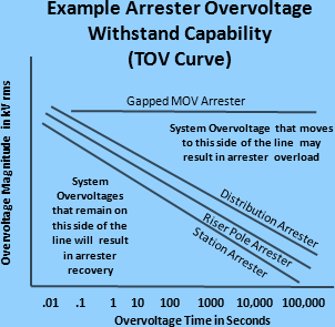
Fig16 TOV CURVES OF DIFFERENT TYPES OF ARRESTER
In the example in Figure 17, the selected distribution arrester would not withstand an overvoltage of an ungrounded or delta system, but would withstand an overvoltage from a uni-grounded and multi-grounded system. However if a gapped MOV arrester was selected, it could withstand even an ungrounded system overvoltage
.
Fig 17 Comparing TOV Curve and Potential System Overvoltage
In distribution systems, selecting an arrester’s MCOV (Maximum Continuous Operating Voltage) or Uc typically involves matching or exceeding the line-to-line voltage, as the duration of potential overvoltages is often unknown, complicating the comparison between system overvoltage and arrester withstand capability. However, this comparison is crucial for choosing the arrester MCOV or Uc in substation applications. This assessment is more precise for transmission systems and substations, where the expected overvoltage magnitude and duration are known.
Transmission Line Arresters
The MCOV or Uc rating selection for transmission line arresters (TLAs) differs from distribution or substation arresters. TLAs aim to protect insulators from back flash during switching or lightning surges. Since overhead insulators are typically self-restoring, the lowest clamping voltage isn’t crucial for preventing flashover. Sometimes, TLAs are sized to minimize energy absorption during switching surges, which is achieved by increasing the MCOV or Uc rating. However, when TLAs are used to mitigate switching surges, their MCOV should align with that of substation arresters.
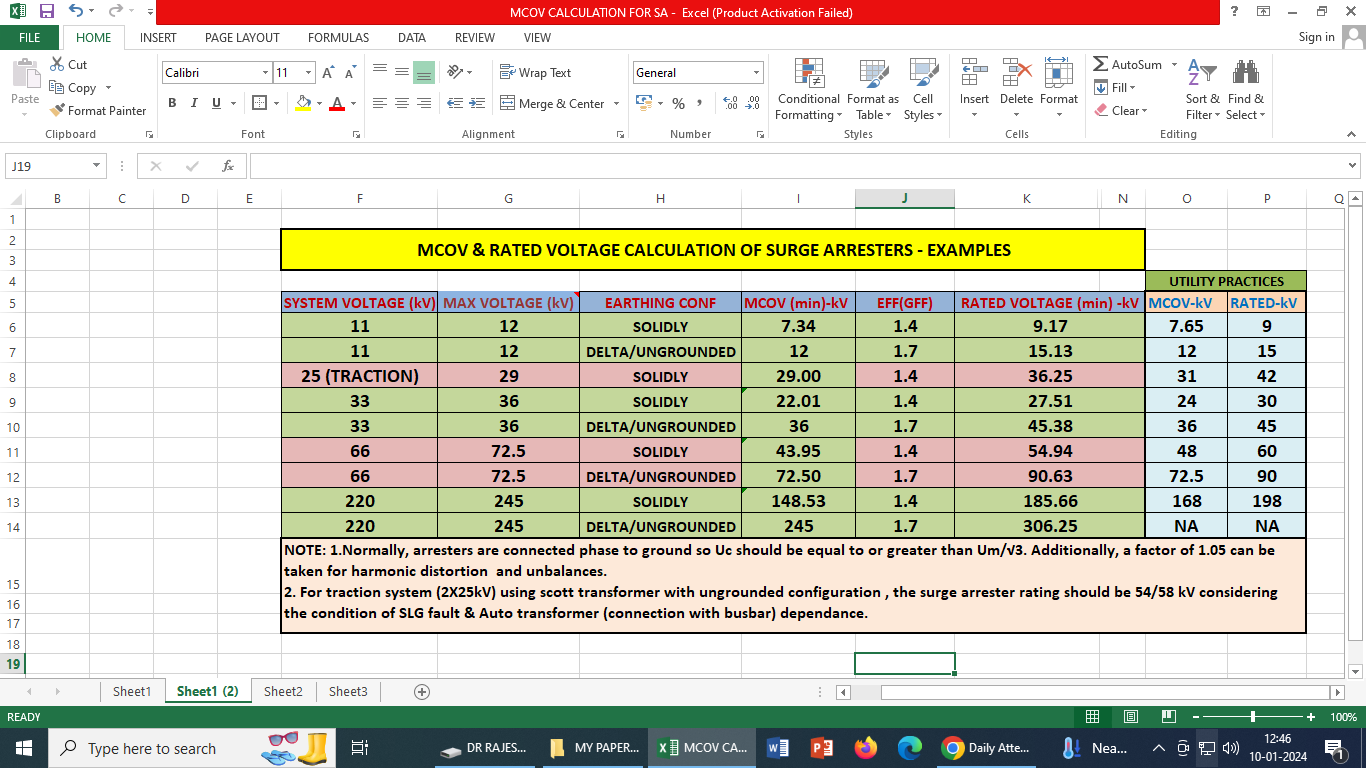
Calculation of MCOV & Rated Voltage of Surge Arresters
The calculations involved in determining the MCOV and rated voltage as well as selected values in utilities are given in table 3 for reference.
TABLE 3 Calculation of MCOV & Rated Voltage of Surge Arresters
Conclusion
The system’s grounding configuration significantly influences the overvoltages during a ground fault. A single phase-to-ground fault can alter the ground potential at the fault site, with the extent of this shift dependent on the grounding setup. This shift is typically minimal in a solidly grounded system with a robust return path. Conversely, in an ungrounded system, there might be a complete offset, causing the phase-to-ground voltage on unfaulted phases to approach the phase-to-phase voltage. It’s advised against using a surge arrester with a rated voltage (Ur) lower than selected to improve margins, as it might lead to insufficient Temporary Overvoltage (TOV) capability.
Reference:
| [1] | IEC 60099-4 Surge arresters – part 4: Metal-oxide surge arresters without gaps for A.C. systems. |
| [2] | IEC 60099-5 Surge arresters – part 5: Selection and application recommendations. |
| [3] | IEEE Std C62.11-2020 Standard for Meta-Oxide Surge Arresters for AC Power Circuit(>1kV) |
| [4] | IEEE Std. 80-2013, IEEE Guide for Safety in AC Substation Grounding, New York, NY: IEEE |
[5] www.arresterworks.com
 | Dr. Rajesh Kumar Arora holds a B. Tech. and a Master’s in Electrical Engineering from Delhi College of Engineering, University of Delhi. He completed his PhD in grounding system design from UPES, Dehradun. He is a certified Energy Manager and Auditor with over 14 years of experience in 400kV and 220kV substations at Delhi Transco Limited (DTL). Additionally, he served as Deputy Director (Transmission and Distribution) at the Delhi Electricity Regulatory Commission for over three years and has contributed to various departments within DTL. Currently, he works in the Design and Engineering department of DTL, with research interests in high voltage technology, grounding systems, protection systems, computer applications, and power distribution automation. |
We use cookies to personalize your experience. By continuing to visit this website you agree to our Terms & Conditions, Privacy Policy and Cookie Policy.