The new age of power flow control: Optimising power flow in transmission networks
By EPR Magazine Editorial May 8, 2021 3:14 pm IST


By EPR Magazine Editorial May 8, 2021 3:14 pm IST

The proliferation of variable renewable generation has led to new challenges for transmission utilities.
The investment and time required to build new lines has re-emphasised the importance of utilising existing grid capacity. Further, existing network capacities remain under-utilised in some cases due to uneven power flows in the network. Smart Wires’ modular power flow control technology, the SmartValveTM, helps utilities capture more value from the grid rapidly and cost-effectively.
The SmartValve can help Indian utilities overcome a variety of modern days’ challenges – optimising line flows, accommodating seasonal variations, integrating more renewables, fulfilling rapid demand growth, improving reliability and saving money – as proven around the world.
The need for power flow control
In meshed transmission and distribution networks, the flow of electricity is guided by the principles of physics, i.e., the electrons take the path of least resistance. When new transmission lines are built to add more capacity, electricity continues to flow through paths of least resistance, which may not be the intended routes. This can lead to congestions on some routes while other routes remain under-utilised. Generation may have to be curtailed due to such congestions. Utilisation of this spare capacity can increase the network’s transfer capacity, resulting in the best use of the available network. The pressure to accommodate renewable generation and increasing demand means the need to dynamically control the flows on the lines becomes a necessity.
Power flow control (PFC) can help unlock this potential. Modular PFC is the insertion of relatively small effective impedance change into the circuit to change the power flowing through it. Smart Wires SmartValveTM technology is the way to achieve this.
Introduction
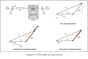
Line compensation may be shunt (e.g. SVC, STATCOM), series (e.g. FSC, TCSC, PST) or combined (e.g. UPFC) based on the application and need. The SmartValve, member of the FACTS family, is a Static Synchronous Series Compensator (SSSC), which is connected in series with the line, to control the power flow on that line.
The SmartValve controls power flow by injecting an adjustable voltage in quadrature with line current (Figure 1), that increases or decreases the effective impedance of the line. The SmartValve is a modular, scalable, relocatable, bidirectional, voltage-agnostic power flow controller, beneficial for operational and investment flexibility.
The SmartValve is a single-phase device available in different standard-sized modules (Figure 2), for e.g., 1 MVAR and 10 MVAR solutions to meet different network needs. It is possible to connect, more than one module in series to get the desired compensation.
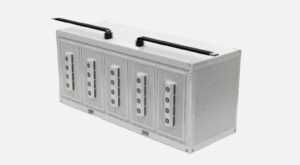
Figure 2: SmartValve 10-3600
The device is maintained at line potential, so no step-up transformer is required. The devices are able to operate at all line voltages that are applicable across transmission and distribution systems between 30 kV and 550 kV (solutions for higher voltages could also be developed). The SmartValve uses an integrated, fast-acting bypass for protection from system faults. Hence, it does not require circuit breaker bypass or a dedicated unit protection system.
Application of the SmartValve
The SmartValve is effective at controlling power flow where there is alternative path for power to travel. This means it is particularly useful for resolving network overloads when one route is taking more power, but there is spare capacity available on an alternative route (Figure 3).

Figure 3: Push & Pull modes of Power Flow Controller
As seen in Figure 3, the SmartValve is installed in series with the transmission line to push power away from the overloaded route or to pull power onto the underutilised circuit and thereby relieve overloads. The same device can operate in both push and pull modes. For example, a utility could have one device in ‘push’ mode and another in ‘pull’ mode when solar output is high, and vice versa for demand at the load centre. This provides the operator with flexibility to manage network flows in different conditions whilst increasing utilisation of the overall system, not just a single line.
Modular PFC (MPFC) technology is used where there is unequal power flow in parallel circuits having unequal lengths (impedance). This may occur both when parallel circuits are at the same voltage or at different voltages. Typical situations where modular power flow control is utilised and add value to the network include:
a) Areas where reinforcing the network has become delayed
The SmartValve can easily be re-deployed. This means that the SmartValve can be installed as a temporary solution whilst reinforcement options are completed. Following the completion of the reinforcement work the devices can be re-used elsewhere in the network.
b) Areas where renewable generation results in very different flows at different times of the day
SmartValve device helps interconnect renewables at sites that were previously considered infeasible by unlocking capacity on the existing network; they enable operators to effectively manage intermittent flows from renewable generation in real-time.
c) Uncertainty in long-term needs for investment
SmartValves help operators control the magnitude and direction of power flow, enabling them to react to seasonal or annual changes in generation and load patterns.
d) Providing series compensation without the risk of subsynchronous resonance (SSR)
The SmartValve is not directly including a series capacitor in the line, therefore reduces the risk of SSR.
Operating & Control Modes
The SmartValve has three distinct modes of operation. The modes during normal operation are determined by the state of the bypass as follows:
a) Monitoring Mode – No voltage is injected into the line in this mode.
b) Injection Mode – In this mode either a positive or negative voltage is injected to the line in quadrature with the line current, having a capacitive or inductive impact on the connected line.
c) Bypass Mode – The internal bypass provides fast protective action during line fault conditions. When in Bypass Mode there is no voltage injected into the line. SmartValve is able to remove the injected line impedance within one millisecond for local detected faults. This mechanism acts to protect device and ensures the devices are transparent to the existing system protection relays.
This fast bypass mechanism removes the inserted impedance from the circuit within one millisecond of a detected fault, which is faster than the response time of distance protection relays. Because the inserted impedance of the converters is removed so quickly, the SmartValve typically does not impact the existing relays and the utility will not normally require any changes to be made to existing distance protection relays. This minimises the effort required to integrate the SmartValve solution into the utility’s system.
SmartValve deployments can be configured in many ways for pre-fault and post-fault response. For example, the deployment can automatically restore to pre-fault operation condition post fault clearance or it can wait to receive operator command to go back to injection mode. The devices can be controlled locally, remotely and can be configured to automatically respond to changing system events if required, using the available control modes. In the Injection operating mode, the SmartValve has three control modes that can be used to manage the level of injected voltage.a) Fixed Voltage Mode – The SmartValve fleet is set to output a fixed voltage injection, either capacitive or reactive. In this control method, the injected impedance will vary as the line current changes.
b) Fixed Impedance Mode – The SmartValve fleet is set to output a fixed impedance. In this control method, the injected voltage will vary as the line current changes to keep the impedance at a set value.
c) Current Control Mode – The SmartValve fleet actively regulates the magnitude of the current towards a set point.
The operating range of a SmartValve 10-3600 as a function of the line current is shown in Figure 4. The outer orange boundary indicates the limit of the voltage injection for a single device; in this case maximum output is ±2,830 Vrms. The injected voltage is fully controllable within the operating band and is independent of the line current or voltage. This means that the device can operate at any point within the grey shaded area reflecting the full operating range of the device. Multiple SmartValves can be connected in series with each other and the capability is additive, meaning two devices provide double the operating range and three provides triple, etc.
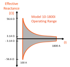
Figure 4: Operating Curve of a SmartValve 10-3600
Comparison with other traditional series compensation devices
SmartValve has been used instead of a variety of alternative network reinforcement solutions, such as phase shifting transformers and to enhance planned network reinforcements such as new overhead lines. There are many ways of comparing different FACTs device, depending on the critical problem being addressed. Different series compensation solutions have been optimised to solve different issues. The SmartValve has been optimised to quickly change between inductive and capacitive modes and to install it quickly and easily. It should be noted when comparing different solutions, it is best to run detailed system studies to establish the correct size and compare the network impact rather than comparing solutions of exactly the same size.
Installation:

Figure 5: Deployment Options for the Smart Valve 1-1800
The SmartValve is series connected so can be installed in any part of the line and has the same electrical effect. Therefore, consideration on location is focused on the practical ground conditions, such as where physical space is available. The devices can be installed in either substation or along the circuit route.
When space is at a premium or constrained, it is possible to split a SmartValve installation at either end of the circuit, or at available locations on the route. The devices can also be stacked when vertical height is not a concern, but the footprint is.
Benefits of SmartValve Technology
a) Modularity and Scalability
• Ability to increase or decrease the number of devices over time
• Ability to time solution delivery with network need, no need to guess needs far into the future
• Inject the desired level of impedance
b) Re-deployability
• Device can be relocated as needs change
• Same device can be installed at multiple voltage levels
• Do not need to change protection settings
c) Flexibility and Speed
• Can be delivered in less than one year
• Multiple different control modes
• Can be run automatically or from a control room as required
d) No Single Point of failure
• If one device stops working, the other devices in the installation will be unaffected
Worldwide Installations & Indian market In India,
Sterlite Power Transmission Limited has partnered with Smart Wires to introduce this innovation to the Indian Grid and is now ready to address the toughest challenge of energy delivery -Power Flow Control.
—–
Author: Biswajit Mukherjee, Amitabh Singhal / Organization: Sterlite Power Transmission Limited, India
Author: Catherine Winning / Organization: Smart Wires, USA
We use cookies to personalize your experience. By continuing to visit this website you agree to our Terms & Conditions, Privacy Policy and Cookie Policy.


-20240706113929.png)