Parameters to maintain substation earthing with calculations
By EPR Magazine Editorial December 20, 2021 2:50 pm IST


By EPR Magazine Editorial December 20, 2021 2:50 pm IST

This article walks us through the key critical parameters to be considered for selecting and working on earthing systems for a substation.
The fundamental role of any substation earthing is to dissipate the short circuit current into the earth without drying out the area and to limit the potential gradient throughout the substation to maintain the step and touch voltages within safe values. There are two features considered during the design of earthing for a substation which is:
Earthing standards:
To calculate the substation earthing design parameters and the potential shock safety limits, a large variety of national and international guidelines are followed across the globe that is:
Parameters considered for earthing of substation
Ground potential rise: An earthing mat is a grounding system formed by a grid of conductors buried horizontally and provide a low impedance path for the earth’s fault current to dissipate into the earth. The earthing grid present in the substation is an electrical connection to the earth at zero-potential reference point. The connection where the earth mat is buried is not ideal due to the resistivity of soil that leads to the flow of current via the grid to the earth, during a typical earth fault condition leading to a potential rise in the system, creates a potential gradient within and around the substation ground area. Ground Potential Rise (GPR) can be defined as the product of ground electrode impedance with respect to zero-earth and the current flowing through that electrode impedance.
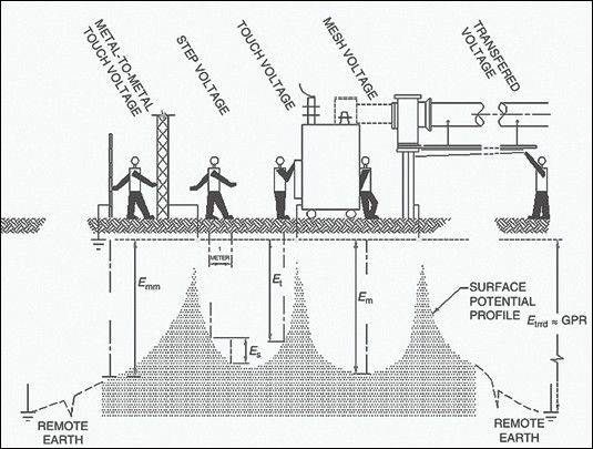
GPR = I0 × Rg: GPR can be controlled by keeping resistance of the earthing grid as low as possible, so that the earth fault conditions are limited for maintaining the step and touch the potential limits. Step potential, mesh potential, and transferred potential plays a vital role in the calculation of an earthing system and to ensure equipment safety as well as human safety.
Step potential: The potential difference between two points on the surface of the earth separated by a distance of one pace that is normally assumed to be one meter in the direction of the maximum potential gradient is known as ‘Step Potential’. Considering a constant body impedance of 1000Ω Step potential can be calculated as
![]()
Where ρs – resistivity of the surface layer & ∁s – scaling factor due to the protective surface layer.
Touch potential: The potential difference between a grounded metallic structure and a point on the earth’s surface at a distance equal to the normal maximum horizontal reach is approximately one meter.
![]()
Where ρs – resistivity of the surface layer & ∁s – scaling factor due to the protective surface layer.
Transferred voltage is a special case of touch potential where the voltage generated is transferred to/from an external point to the substation.
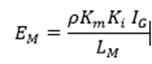
Mesh potential: Mesh potential is the maximum touch voltage generated within a mesh of an earth grid. The mesh potential is defined as the product of the soil resistivity (ρ), the configuration of the grid (Km), a correction factor (Ki), errors that occurred due to assumptions, and the average current per unit flowing through the grounding conductor IG/LM
Earthing system design considerations
In any Substation earthing layout, the earthing system is made up of an earthing grid consisting of cross bonded conductors. These conductors must possess the adequate thermal capacity to provide sufficient time for the fault currents to flow through them. The earthing conductors should also be mechanically sturdy and corrosive resistant. The conductors are normally buried horizontally at a depth between 0.5m to 1m ensuring the earthing conductor has adequate mechanical protection. The surroundings shall not dry out; hence, it is placed below the frost line.
For proper designing of the earthing system, certain parameters such as the conductor size, grid resistance, and the maximum grid currents are considered.
Size of the conductor: The minimum size of a conductor required during earthing can be determined by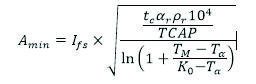
Where short circuit current (lfs), duration of fault current (tc), thermal resistivity (ar), soil resistivity (prl), the thermal capacity of copper (TCAP), maximum allowed temperature (Tm), and ambient temperature (Ta) are the factors affecting the size of the conductors.
The fall of the potential test method is used to measure the ground grid resistance. The resistance obtained from the ratio of the earth’s potential rise and the current causing it is called the grid resistance. The grid resistance can be calculated as
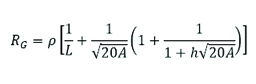
Where A= area of the grid, p= resistivity, L = length of the grid
The maximum grid current is the ratio of current flowing between the earth grid and the surrounding earth to the symmetrical fault current. This current is affected by the fault current division factor. The maximum grid current can be calculated as:
Where – current flowing through the grid, – decrement factor
Vertically driven rods
The electrodes used when the soil resistivity of the ground is low and it can penetrate beneath the layer where the soil resistivity is high are vertically driven rods. The length of the earth rod is calculated in such a way that it reaches more stable layers into the earth below. These earth rods would stabilize the earth grid resistance during the changes in seasonal resistivity.
Substation fences
Earthing around the substation is important to avoid dangerous touch potentials and fatal electric shocks. Metallic fences are built up around the substation. These fences also prevent access to the general public. Earthing fences can be built in two ways i.e., by connecting the earth grid electrically with the fence within the grid or by independently earthing the fence and placing it outside the earth grid with an acceptably low potential gradient.
Other substation earthing
The ground potential rise at any substation can be subsided by overhead line earth wires where the wires are connected to the earth grid diverting the fault current towards the foot of the earthing tower. Cable armouring is done to divert the earth fault current towards a remote earthing grid.
Conclusion
The design of grounding in a substation is a continuous and a vital process as the safety of the equipment as well as the workers is dependent on the design parameters. Proper grounding of a substation provides a safe environment to the personnel in the vicinity of grounded facilities. There are few other elements involved in the process of designing which include the design refinement, effects of directly buried pipes, and control of power cable grounding, surge arrester grounding, and installation considerations. An ideal grounded substation is an optimally designed safe grid, designed using accurate modelling techniques, enabling material and labour savings while meeting all the safety standards. This improves field safety, better quality installation, constructability, and efficiency in all types of weather conditions.
This article is part of our series of articles on Lightning Arresters, Surge Protection and Earthing; you can read more with the following links:
Lightning Protection System Design and Products
Surge Protection Devices (SPD)
Lightning Protection Zones and their Application to SPD Selection
For more details, contact:
Email: info@axis-india.com
Website: www.axis-india.com
Axis, Plot No.104 C, Kandivali Co-op Industrial Estate Ltd., Kandivali (W), Mumbai-400067, Maharastra, India.
We use cookies to personalize your experience. By continuing to visit this website you agree to our Terms & Conditions, Privacy Policy and Cookie Policy.


-20240706113929.png)