Understanding Errors in Current Transformers
By EPR Magazine Editorial January 3, 2022 12:08 pm IST


By EPR Magazine Editorial January 3, 2022 12:08 pm IST

In this article, we will understand various errors that are experienced in Current Transformer and also possible methods to compensate these errors.
Current transformer are used in electrical power system for stepping down higher values of currents of the system for metering as well as protection purpose.In the basic instrument-grade current transformer, a single primary conductor passes through the core. The secondary winding has multiple turns to provide a lower output current, as shown in the diagram. However, it is important to have the same turn’s ratio as the current ratio. But in a current transformer due to the effect on its characteristics there is always a difference between the ideal and obtained values. Also, the phase displacement should be 180°. In this article, we will understand various errors that are experienced in Current Transformer and also possible methods to compensate these errors.Any measurements based on the current, such as power or energy, would similarly be affected.
Errors in Current Transformer
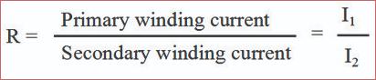
Before going into further discussion, it is better to understand some of the basic but important parameters. They are as follows:
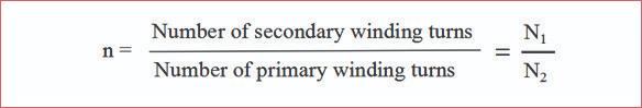
The construction of the current transformer depends on the turn’s ratio. Based on the primary current and number of turns on the core, the secondary current is been stepped down. Let us understand this by an example.
Consider that we are designing a 1000/5A CT. The number of turns at primary is usually one due to limitation of the conductor size, which is larger, due to higher current. For deciding the number of secondary turns we will take the ratio of 1000/5 i.e. 200.Therefore, the secondary winding shall consist of two hundred turns on the core. Thus, the turn’s ratio will be 200:1
Ratio Error
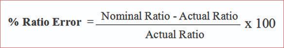
With the similar example of 1000/5A CT, in ideal condition, 5A output at secondary is expected. However, in actual condition, the secondary current can vary to a value higher or lower value than 5A. This is due to the Turns Ratio Error.
How to calculate Ratio Error?
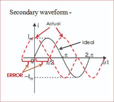
Phase Error (θ)
Ideally the angle between the primary current and secondary current must be exactly in phase by 180°. However, in the actual output there is some deviation from 180 °. This deviation is called phase angle error.
Compensation of Errors
The major contributor for occurrence of these errors is Copper Loss and Core Loss in the Current transformer. The copper losses can be compensated by changing the number of turns of the secondary winding whereas the core losses are mainly due to the eddy current and Hysteresis loss in the core material of Current transformer.
Considering the case of 1000/5A CT, with the turn’s ratio of 200: 1, we take 200 nos. of turns on the secondary side of CT. If the secondary output current is 4.9A, the ratio error is of -2 percent. Now, in order to compensate this error, if we increase one turn , the output current is 5.1A i.e. the ratio error is still +2 percent. In either case, the error is still present.
Solution is we take a “Run”. This means that we divide the secondary conductor into two parts and run them in parallel with their ends shorted as shown below
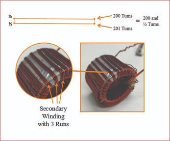
Thus, we can take 200 turns for one conductor and 201 turns for the parallel conductor. This solution helps to compensate the Ratio Error at a permissible limit bringing the actual output current close to 5A.
The core loss component can be divided into Eddy Current and Hysteresis loss. The eddy current loss can be compensated by use of laminated core. The Hysteresis losses mainly depend on the material of the core. By use of various high permeable, low reluctance metals such as MU metal, CRGO and Nanocrystalline the hysteresis loss can be compensated to minimum value.
We use cookies to personalize your experience. By continuing to visit this website you agree to our Terms & Conditions, Privacy Policy and Cookie Policy.


-20240706113929.png)