Uncovering the invisible
By EPR Magazine Editorial June 12, 2017 3:05 pm IST
By EPR Magazine Editorial June 12, 2017 3:05 pm IST

Why the integrity of the ground grid needs to be checked
The grounding system is an important component for the correct function of a substation. When it is not in suitable condition, there is an increased safety risk for people and control and measurement equipment may be affected as well. Different standard tests give an indication of the overall functionality of the ground grid but they cannot determine the precise internal condition of the grid itself.
The commissioning and maintenance strategy for electrical substations normally includes testing that assesses the condition of the ground grid: Measurements of the soil resistivity are done during the design stage; ground grid impedance and step and touch voltages are checked regularly. However, these tests cannot reveal the condition of the grid’s connections that affect its continuity. Therefore, a ground grid integrity test should be done in order to assess it.
Invisible danger in older substations
The integrity test for the ground grid basically consists of verifying the continuity between two different points on the grid. It ensures that the internal connections within the grid are in a good enough condition to dissipate fault currents. Such a test is particularly important in older substations where the grid has been buried for a long period of time and it is not possible to verify the connections visually. In addition, soil with low resistance is often chosen for constructing substations, which can corrode the grid’s metallic components over time. In the “IEEE Guide for Measuring Earth Resistivity, Ground Impedance, and Earth Surface Potentials of a Grounding System” (IEEE 81 standard) different methods for measuring the continuity are mentioned. A 230 kV substation was examined using the high-current test method.
A practical experience
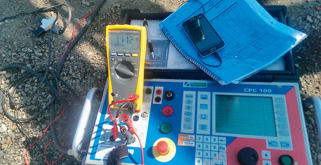
The resistances between different reference and test points were measured in the 230 kV substation. The equipment that was used during the test was a CPC 100 for delivering the 300 A DC that was required, a DC voltmeter, a DC clamp ammeter and markers for identifying the test points (Figure 2).The resistances per meter were determined for several test points in the substation as shown in Figure 3. The measurement showed no significant deviations between the relative resistances within the substation. All of the values were between 0.4 m?/m and 1.2 m?/m.
Further investigation is recommended if the test points show a significantly higher resistance value compared with other test points. The test point should be revealed in order to carry out a visual inspection.
In addition to measuring the impedance of the ground grid and the step and touch voltages of the substation, it is also important to be aware of the integrity of the grid itself. An integrity test for verifying the continuity of the grid at any of its points should be a standard procedure in the maintenance strategy of a substation. Thanks to the multi-functionality of the CPC 100, ground impedance, step and touch voltages and integrity tests can be carried out with one test set.
We use cookies to personalize your experience. By continuing to visit this website you agree to our Terms & Conditions, Privacy Policy and Cookie Policy.