Technical note on high-voltage in a current transformer
By EPR Magazine Editorial December 12, 2019 4:34 pm IST


By EPR Magazine Editorial December 12, 2019 4:34 pm IST

Introduction:
Current Transformer (CT) is an instrument transformer that simply steps down the high current and provides it in 5A / 1A range for measurement. CT consists of a toroidal core with primary winding as a conductor passing through the core center. Depending on the required secondary current, number of turns is wound on the core as the secondary winding. The As per IEEE

Transformation ratio
Just like other transformers, there will be load on CT secondary and that load is called Burden.
Why Load on CT is called Burden?
The reason why we called load on CT as a burden is that, like a normal transformer, CT secondary can’t be kept open. As high current is steppeddown to lower value, open CT secondary will cause 0A current in secondary, which will ultimately lead to a high voltage which may burn the CT secondary winding and can damage the system. So it is necessary to load the CT secondary continuously and ultimately it acts a burden on CT, and that’s why the load on CT is named as a burden.
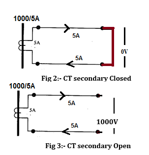
In Fig 2.circuit, CT secondary is short- circuited when a no-load condition occurs. Due to this 5 a current, flows throughthe loop but the voltage iszero because of the shorting of CT terminals.
In Fig 3.Circuit CT secondary is kept open with no load condition, causing the Voltage to rise up to 1000V and making CT secondary current zero due to open circuit condition. This high voltage will lead to insulation failure or permanently damage the insulation causing inaccurate reading after connecting to the instrument and in the worst case; it can lead to burning of the CT coil.
The load connected to CT secondary is mentioned in VA (normally), as in a transformer, the connected load is of Resistive, capacitive or inductive type.
Burden of CT can be specified as Volt-Ampere absorbed at certain power factor i.e. the VA that can be consumed by the load. The burden can also be expressed as total Impedance in terms of ohms connected on secondary of CT i.e. pilot conductor and instrument burden (I2 x R=VA).
To simplify the above point, let us take an example: for a 100/5A CT with a Burden of 0.4ohm impedance, the burden can be expressed as 10VA at 5A secondary current “I2 x R = 52x.4 = 10VA”. In industries, VA is more commonly used unit for CT burden Burdens on CT
There are 2 types of CT.
1. Metering Type and 2.Protection type.
Burden for Metering type CT = Total Burden of Meters (Digital/Analog Ammeter, Voltmeter, Power Meter, MFM, Transducer) which are in series with CT + The total VA of the Cables connecting CT and the Meters.
Burden of Cable can be calculated as “Current Square x Resistance of cable per length x 2 times the length of cable” i.e.
Cable VA = (2L x R x I^2).
Example: If a 250/5A CT is connected to a load of 0.02 ohm resistance through cable 2-meters long, then the VA burden of Cable will be
Cable VA= 5^2 x 0.02 x 2 x 2=2VA.
The cable burden will be as per its cross-section area and length. Resistance of Cable depends on the gauge and length of cable. Burden of different meters are mentioned in their respective datasheet and catalog provided by the manufactures.
For better understanding burden of various meters is mentioned in table 1.
| Meters | Burden | ||
| Analog Meters | 1VA | ||
| Digital Meters | 0.5VA | ||
| Current Coil of Watt Meter /VAR Meter | 1.5VA | ||
| Current coil of energy Meter | 2VA | ||
| Current coil of PF Meter | 2.5VA | ||
| Current coil of Tri- Vector Meter | 5VA | ||
|
Table.1 |
|||
So if you are using an analog meter with 2m cable then the total burden on CT will be 1VA+ 2VA= 3VA.
Burden for Protection class CT will be similar to Metering type only instead of meters the burden will be of individual relays. Burden of Protection class CT= “Total VA burden of cables connecting CT to relay + Total VA of Individual Relays”.Burden of various Relays or protective system is mentioned in table 2
| Protective System | I2 | VA | Class |
| Per–current for phase and Earth fault Relay | 1A | 2.5 | 10P20/5P20 |
| 5A | 7.5 | 10P20/5P20 | |
| Unrestricted earth fault Relay | 1A | 2.5 | 10P20/5P20 |
| 5A | 7.5 | 10P20/5P20 | |
| Motor Protection Relay | 1A/5A | 5 | 5P10 |
| IDMT Earth Fault Relay | 1A/5A | 15 | 10P10 |
|
Table 2. |
|||
Effect of Burden on CT Accuracy and IS
For any CT, Instrument Security Factor (ISF) is nothing but the ratio of Maximum limited Primary current to rated Primary Current.
Basically, the ISF is used to protect the load connected in the secondary side of the metering CT i.e. meters etc. The core of CT will get saturated at higher current i.e. 5 to 10 times (depends on ISF) higher than the rated primary current.
If ISF of a 100/5 CT is 5 then at 500A CT will provide equivalent 25A in the secondary side but once the current cross beyond that i.e. 600A or 1000A the core will get saturated and themeter will get protected.
If CT Burden is chosen much higher than required, then the CT accuracy deceases for less than 100percent load and increases for more than 120percent of load or we can say the accuracy of CT get out of phase and also the ISF of CT gets an increase (refer to table 3&4). Designing CT for higher burden increases the saturation characteristic of core causing the risk for the load connected in CT secondary and also lead to CT failure. If a CT with 10 VA design against the required Burden 2.5VA will lead to increase ISF by 4 times i.e. if ISF for 10VA is claimed as 5 that means saturation Voltage will be 10Volts but if operated at 2.5VA then Saturation voltage will be 2.5Volts against 10Volts which leads the increase in ISF up to 20. So if high current flows then CT will provide 20 times secondary output current leading a meter or circuit connected on secondary to fail or get damaged it. Let’s check the accuracy of 100/5A CT 10VA class 1 tested at full rated burden 10VA and tested at rated burden of 2.5VA.
Error Measurement:-
| Rated I1 | Ratio Error | Phase Error | Accuracy Class | |
| 120percent | -0.07 | + 21 min | 0.5 | |
| 100percent | -0.05 | + 19 min | 0.5 | |
| 20percent | -1.47 | + 65 min | 1.0 | |
| 5percent | -3 | + 134 min | 1.0 | |
|
Table 3.
|
||||
100/5A CT 10V Class 1 tested at Burden of 2.5VA
Error Measurement: –
| Rated I1 | Ratio Error | Phase Error | Accuracy Class |
| 120percent | 2.77 | + 37 min | OUT |
| 100percent | 2.75 | + 43 min | OUT |
| 20percent | 2.59 | + 69 min | OUT |
| 5percent | 2.4 | + 102 min | 1.0 |
|
Table 4. |
|||
From the above Test it is clear that the CT design with a higher burden if used at a lower burden then that will leads to higher error in measurement even if CT is at 100percent of rated Primary Current and also that CT accuracy gets even better when operated at nearly rated Burden even at 50 per cent of rated primary current.
It is often seen that load on CT is majorly only Meters and Cable (max. It can be 10VA for metering CT), so we suggest that the rated Burden for the metering CT shall be a standard value and as close to the connected Burden as possible.
The Core thickness of CT depends on the VA. Therefore for higher VA and for smaller rating CT, core thickness will increase, which leads to difficulties in mounting of CT in respective applications.
By Rahul Pansare | Product Manager Analog | Rishabh Instruments Pvt. Ltd
We use cookies to personalize your experience. By continuing to visit this website you agree to our Terms & Conditions, Privacy Policy and Cookie Policy.


-20240706113929.png)