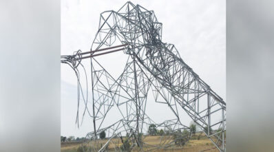
Electricity is the backbone of the modern world. Electricity produced by power plants is transmitted over long distances using power transmission towers. Transmission towers are prone to collapse under heavy wind loads. Due to practical limitations in design and resource constraints, transmission line towers can only be constructed to withstand some calamities. Consequently, failure of towers is observed during natural calamities such as storms, typhoons, strong winds, heavy rain, floods, earthquakes, landslides, and man-made disasters like sabotage.
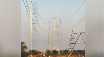
Earlier, these breakdowns were being attended to with the restoration method, which involved debris removal, casting or repairing of concrete foundations, arrangement of all tower parts and line material, erections, and stringing. These activities took at least 4 to 6 weeks, depending on the nature of the failure, owing to the settling time required for cement concrete in foundations. Consequently, the power system was prone to long breakdowns. This, coupled with the fact that the transmission system in the country has low redundancy, created a grave situation in attending to the tower collapse or any line diversion. A unique method to substantially overcome tower collapse problems is using an Emergency Restoration System (ERS). ERS are temporary towers that are primarily used on electrical transmission lines. ERS are modular structures made of aluminium alloy, hot-dip galvanised structural steel, or a combination of high-strength aluminium alloy and hot-dip galvanised structural steel. Aluminium alloy is preferred due to its lightweight. They are corrosion-free. They are quick-erect aluminium towers that can be raised in the field in less than a day and are used to address power outages or tripping in power lines during emergencies, meet maintenance requirements, divert lines, and serve a variety of other purposes. It is a proven technique for disaster management in the transmission sector. Key reason for tower failure
The high wind velocity during storms, cyclones, and local phenomena like whirlwinds, etc., might have exceeded the wind speed for which the tower is designed. This type of wind is difficult to predict. The probability of such occurrences is low, and the tower design will be uneconomical if such a situation is considered in the design.
Theft or sabotage of tower members: Generally, the theft of secondary members (connected with one or two bolts) of the towers makes the tower structurally weak, eventually leading to failure during high-speed wind, storms, whirlwinds, cyclones, avalanches, and other natural disasters.
Even miscreants destroy the tower by cutting or blasting the leading members, cutting legs during design or construction, and the O and M stages.
A lack of proper soil investigation and a deficiency in the design or construction of the towers’ foundation may also fail. Sometimes, proper protection is not provided for the foundation of towers on steep slopes/hilly terrain. Many times, landslides cause erosion of the soil below the foundation, which in turn causes the failure of the foundation and, subsequently, the failure of towers. The tower foundation failure (near the river bank) is due to soil erosion below the foundation by flash floods or a change in the river course.
Secondly, Shear failure of stubs of leg members of towers due to torsional forces on account of the sinking of some of the legs. Advantages of ERS (keep it in a coloured patch /box)
Thebenefits of using ERS are enumerated below: (i) ERS structure being light in weight and easy to transport, handle, and erect (ii) No foundation is required.
(iii) Bypassing critical towers; (iv) Inventory reduction; (v) IEEE 1070 standardised design;
Advertising
(vi) Modular design and very user-friendly; (e) Quick restoration of the collapsed portion of the transmission line. (vii) ERS can be in service for a longer period, thereby allowing a reasonable time for restoration of the affected transmission line; no civil engineering work is required; (viii) the high political and social costs can be avoided. ERS Components
The emergency restoration structure is designed for easy handling and transportation. The column section is the heaviest component. The emergency restoration system includes insulators and conductor hardware. Polymer suspension and post insulators are of high strength and low weight, which allows them to be easily transported over rugged terrain, including hilly areas. All components can be easily transported by open truck to any nearby location, and after that, they can be shifted to various tower locations by head-loading.
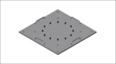
The structures are normally tested for strength, compression (columns), bending (columns), torsion strength, ultimate strength bending (bolts and welds), load (box sections and guy plates), and bucking (columns) as per the governing standard. Apart from the structural tests, the gimbals are also tested for articulations, compression, and transverse. The major components of a typical ERS are given below: Foundation Plate: It supports the tower by distributing its weight evenly to the ground. It is placed directly on the ground without needing a concrete foundation. It is intended for direct placement on flat or slightly sloped (maximum 40°) ground. Its weight is 250 kg, it provides 2.32 square metres of bearing surface, and it can be pinned to normal ground using 25-mm-diameter reinforcing rods of about 1500 mm in length. The foundation plate shall be designed to rest on the ground surface with anchors or metal stakes to avoid sliding. It should be made of lightweight, high-strength material. The base area of the foundation plate shall be designed to work safely with a minimum earth-bearing capacity, considering the swampy area. For loose soil, the foundation plate can be placed on four no. Screws or marsh anchors driven in the ground increase the soil’s bearing strength.
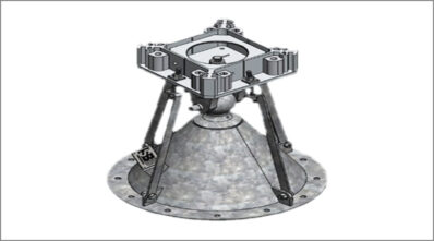
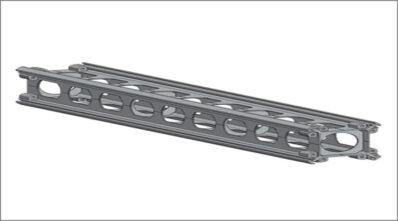
It consists of a fixed cone and a pivoting aluminium plate.The first section above the foundation plate is the gimble joint. It can be rotated in four major axes to allow horizontal column assembly. It allows the tower to move under various loads to avoid bending. The gimble joint and the required column section can be bolted together. The gimbal joint or articulation must be designed so that it can be fixed to the foundation plate and allow structures to be assembled over it. It will allow leaning and rotation in all directions. It shall minimise column eccentricity and eliminate torsional loading on structures due to its rotational capability. It should be made of lightweight, high-strength material. Turnbuckles or alternate means of temporary fixing and alignment must be provided. Column Section Mast Section: It includes 9 openings on each side to allow attachment of a wide range of accessories, like swivel guy plates, insulators, brackets, platforms, etc. These are made of lightweight aluminium alloy, a high-strength material, and are available in different lengths. They can be erected one by one to reach the required height of the structure. The column may have diagonal bracings and diagonal bracings and diagonals positioned in a manner to facilitate tower climbing. The box section shall be of such design that it allows attachment or mounting of insulators and guy wires to the structure. It shall be assembled between column structures and have predetermined holes on the sides to allow attachment of insulators and guy wires. Suitable provisions shall also be made on the ERS tower for the installation of earth wire as required. Guy plate or swivel guy plate, Box Section or Connecting Box, and Provisions for Earth Wire: The design of the guy plate shall be such that it shall allow the attachment of insulators and guy wires to the structure. It shall be assembled between two column structures and have predetermined holes to allow attachment of insulators and guy wires. Depending upon the requirement, the angle of the guy plate shall be 0/0, 0/45, or 45/45. It must be constructed of lightweight, high-strength material. Different suppliers may use different types of guy plates. Other methods of simultaneously attaching insulators and guy wires to the structure in various directions are also acceptable. The swivel guy plate is used to attach guy wires and guy strain insulators to the towers.
The Emergency Restoration Technology (ERS) is a specialised system that allows transmission towers to be replaced by establishing a bypass, allowing electricity transmission to resume significantly faster than with regular techniques. We can avoid long periods of service disruption by employing this system. When a high-voltage transmission line fails due to one or more damaged structures, the responsible utility suffers massive monetary losses as well as hundreds of hours of non-transmission (outage). Given that overall losses and/or damages are directly proportional to the duration of the outage, time is an important component in restoring or repairing the damaged or fallen structure.
For more details visit: https://www.netc.org.in/


-20240706113929.png)