Quick disaster management of damaged transmission lines through ERS
By EPR Magazine Editorial March 11, 2023 12:38 pm IST


By EPR Magazine Editorial March 11, 2023 12:38 pm IST

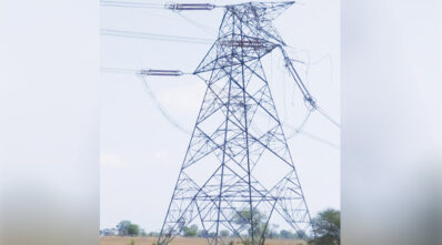
Electricity is the backbone of the modern world. Electricity produced by power plants is transmitted over long distances using power transmission towers. Transmission towers are prone to collapse under heavy wind loads. Due to practical design limitations and resource constraints, transmission line towers cannot be constructed to withstand all types of calamities. Consequently, towers’ failure is observed during natural calamities such as storms, typhoons, strong winds, heavy rain, floods, earthquakes, landslides, and man-made disasters like sabotage.
Earlier, these breakdowns were being addressed with the conventional restoration method, which involved debris removal, casting or repairing of concrete and hot-dip foundations, arrangement of all tower parts and line erections, erections and These activities took at least 4 to 6 weeks, depending on the nature of the failure, owing to the settling time required for cement concrete in foundations. Consequently, the power system was prone to lengthy breakdowns. This, coupled with the fact that the transmission system in the country has low redundancy, created gravitation to attend to the tower collapse or any line diversion. A unique method to substantially overcome tower collapse problems is using an Emergency Restoration System (ERS). ERS are temporary towers that are primarily used in electrical transmission lines. ERS structure erection is made of aluminium alloy, hot-dip galvanised structural steel, or a combination of high-strength aluminium alloy or Hot Dip Galvanised Structural Steel. Aluminium alloy is preferred due to its lightweight nature. They are corrosion-free. They are quick-erect aluminium towers that can be raised in the field in less than a day. They address power outages or tripping in power lines during emergencies, meet maintenance requirements, divert lines, and serve various other purposes. It is a proven technique for disaster management in the transmission sector.
Below are some reasons that can potentially lead to tower failure:
The advantages of using ERS are that they are light in weight, easy to transport and handle, and can be erected easily. It requires no foundation. It can bypass critical towers and offer inventory reduction. They are made with modular designs per the IEEE 1070 standards and are user-friendly. They are known for their quick restoration capabilities for collapsed transmission lines.
Moreover, ERS can be in service for a longer period, thereby allowing a reasonable time to restore the affected transmission line, and it doesn’t require civil engineering work. Its installation can avert any high political and social costs.
Components of ERS
The emergency restoration structure is designed for easy handling and transportation. The column section is the heaviest component. The emergency restoration system includes insulators and conductor hardware. Polymer suspension and post insulators are of high strength and low weight, which allows them to be easily transported over difficult terrain, including hilly areas. All the components can be easily transported by open truck to any nearby location and can be shifted to various tower locations by head-loading.
The structures are normally tested for strength, compression (columns), bending (columns), torsion strength, ultimate strength bending (bolts and welds), load (box sections and guy plates), and bucking (columns) as per the governing standard. Apart from the structural tests, the gimbals are also tested for articulations, compression, and transverse.
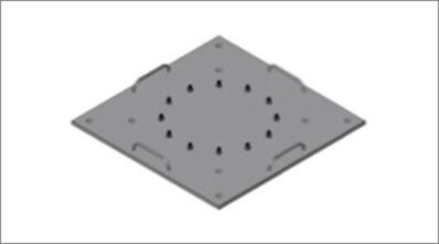
The major components of a typical ERSFoundation Plate: It distributes its weight evenly and is placed directly on the ground without needing a concrete foundation. It is intended for direct placement on flat or slightly sloped (maximum 40°) ground. Its weight is 250 kg, it provides 2.32 sq. m of bearing surface, and it can be pinned to normal ground using 25-mm-diameter reinforcing rods of about 1500 mm in length. The foundation plate shall be designed to rest on the ground surface with anchors or metal stakes to avoid sliding. It must be constructed of lightweight, high-strength material. The base area of the foundation plate shall be designed to work safely with a minimum earth-bearing capacity considering the swampy area. For loose soil, the foundation plate can be placed on 4 No. screws or marsh anchors driven in the ground to increase the bearing strength of the soil.
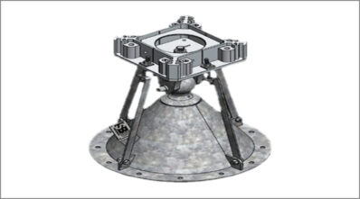
Gimbal joint, articulation base: It consists of a fixed cone and pivoting aluminium plate. The first section above the foundation plate is a gimble joint. It can be rotated in four major axes to allow horizontal column assembly. It further allows the tower to move under various loads to avoid bending. The gimble joint and the required column section can be bolted together. The gimbal joint or articulation shall be of such a design that it can be fixed to the foundation plate, and it shall allow the assembly of structures over itself. It will allow leaning and rotation in all directions. It shall minimise column eccentricity and eliminate torsional loading on structures due to its rotational capability. It must be constructed of lightweight, high-strength material. Turnbuckles or alternate means of temporary fixing and alignment must be provided.
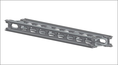
Column section-mast section
It includes nine openings on each side to accommodate various accessories like swivel guy plates, insulators, brackets, platforms, etc. These are made of lightweight aluminium alloy, a high-strength material, and are available in different lengths. They can be erected one by one to reach the required structure height. The column may have diagonal bracing and diagonal bracing positioned to facilitate tower climbing and the mounting of insulators and guy wires to the structure.
Box Section (if required) shall be of such design that it allows attachment. It shall be assembled between column structures and have predetermined holes on the sides to allow insulators and guy wires to be attached. Suitable provisions shall also be made on the ERS tower for installing earth wire as required.
Guy plate, swivel guy plate, Box Section, Connecting Box, and Provisions for Earth Wire: The guy plate’s design shall allow the attachment of insulators and guy wires to the structure. It shall be assembled between two column structures and have predetermined holes to allow insulators and guy wires to be attached. Depending upon the requirement, the angle of the guy plate shall be 0/0, 0/45, or 45/45. It must be constructed of lightweight, high-strength material. Different suppliers may use different types of guy plates. Other methods of simultaneously attaching insulators and guy wires to the structure in various directions are also acceptable. The swivel guy plate is used to attach guy wires and guy strain insulators to the towers. Using an effective emergency restoration plan, the damaged or fallen transmission structures (towers or poles) can be replaced in a few hours, depending on the nature and depth of the damage. Proper planning not only maximises restoration efficiency but can also minimise inventory levels. For utilities, having an effective emergency restoration plan can help control the financial impact of losses due to weather-related power outages.
Conclusion
An exhaustive plan of effective emergency restoration procedures capable of being activated at short notice must be in place with all utility companies. These procedures must be based on knowledge of stock materials in storage, a trained workforce, available equipment, and resource mobilisation while responding to power blackouts caused by nature, such as hill sliding, soil erosion, cyclones, heavy storm super cyclones, flash floods, etc. Utilities can save significant revenue and penalties by utilising ERS, and damaged or diverted transmission lines can be restored immediately.
Authored by – Subhash Chandar Taneja, Director-Projects, NETCL/ED POWERGRID
We use cookies to personalize your experience. By continuing to visit this website you agree to our Terms & Conditions, Privacy Policy and Cookie Policy.


-20240706113929.png)